The Fab Academy 2014
Digital Fabrication Laboratory. Department of Architecture.
Institute of Technology. EPS-CEU San Pablo CEU University
Adolfo Gutiérrez Sánchez
Architect
The Fab Academy 2014 Digital Fabrication Laboratory. Department of Architecture. Institute of Technology. EPS-CEU San Pablo CEU University |
Adolfo Gutiérrez Sánchez Architect |
|||
| Home | Portfolio | Files | ||
| COMPUTER-CONTROLLED CUTTING |
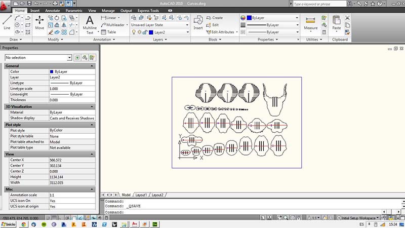
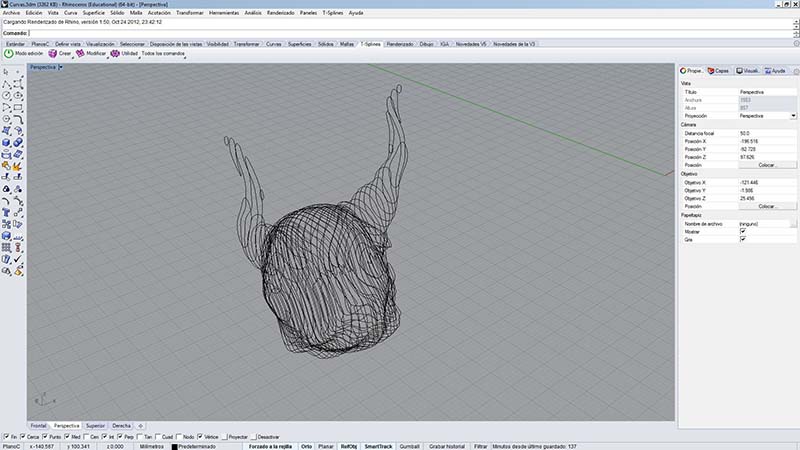
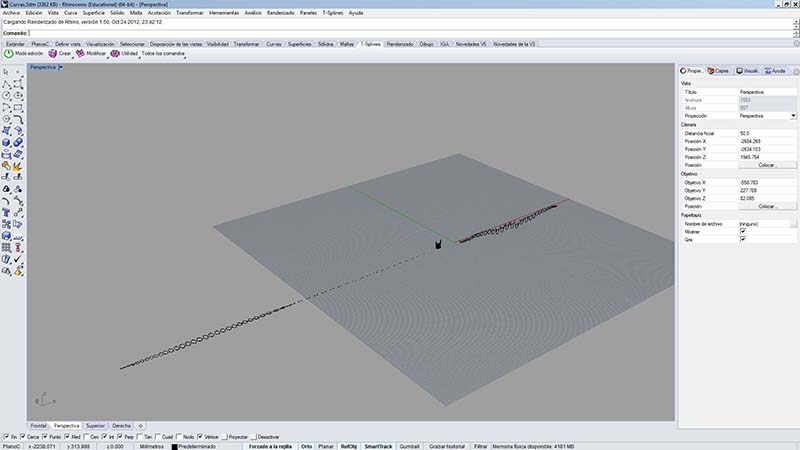
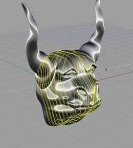
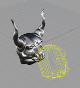
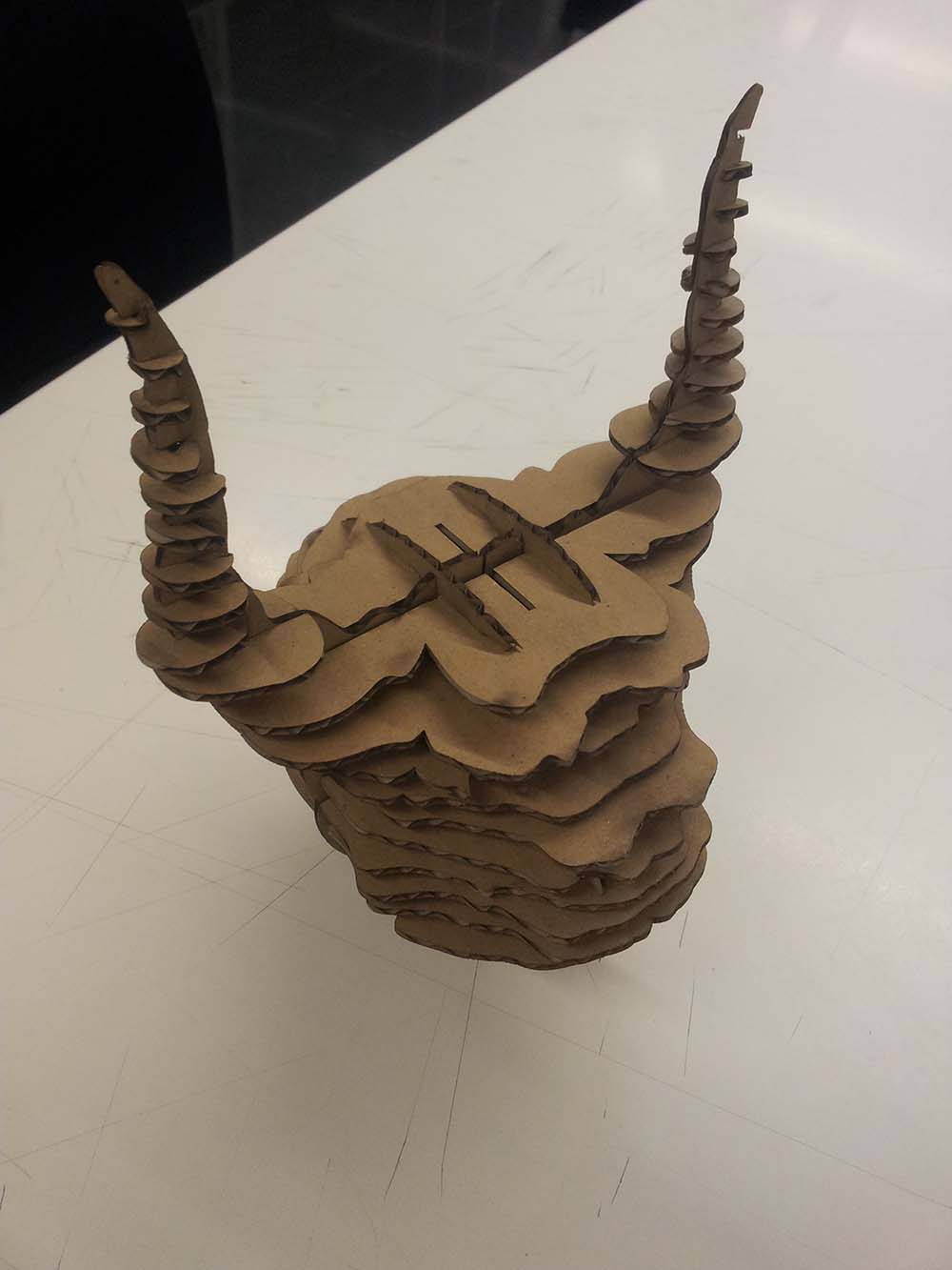
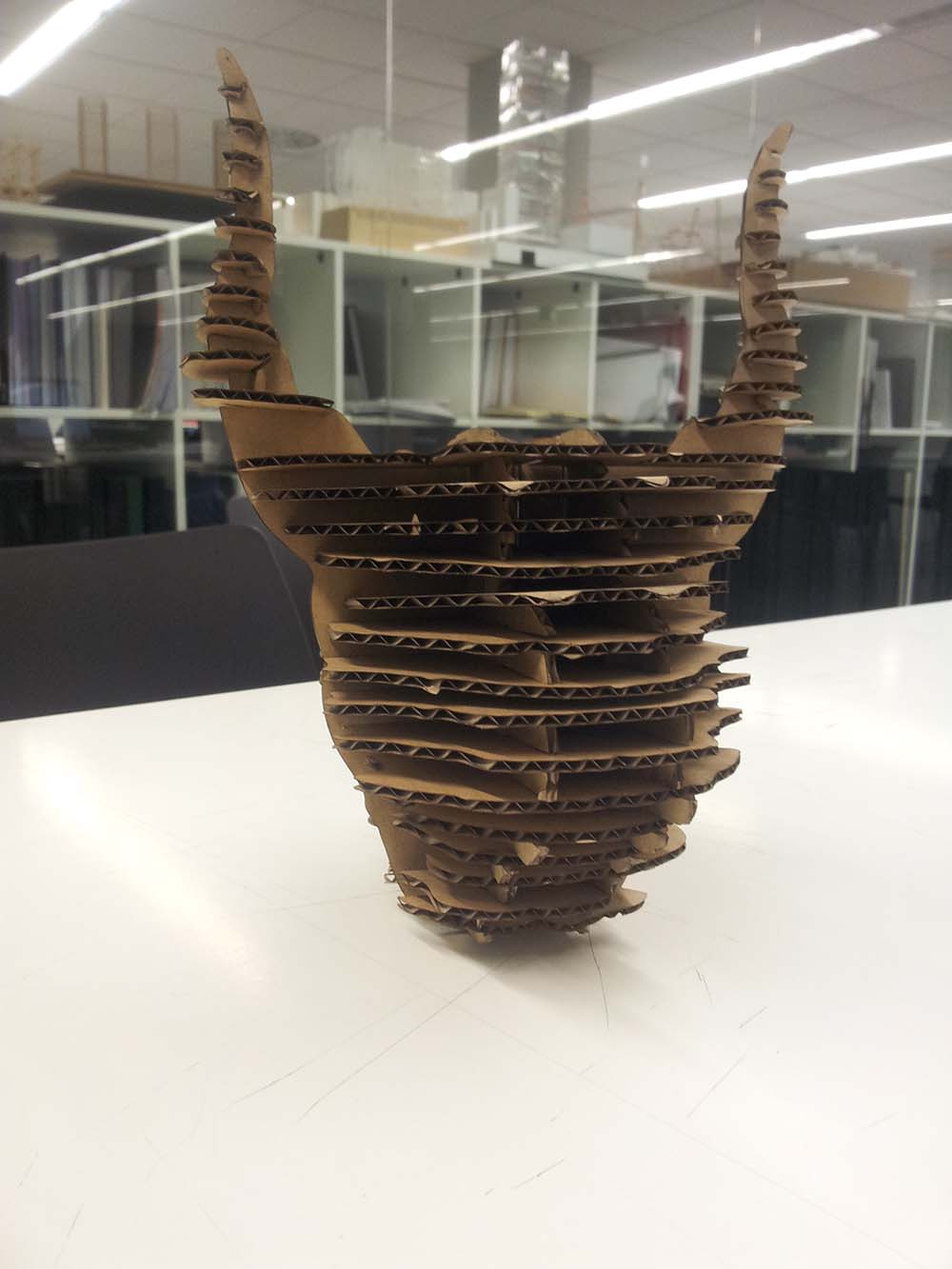
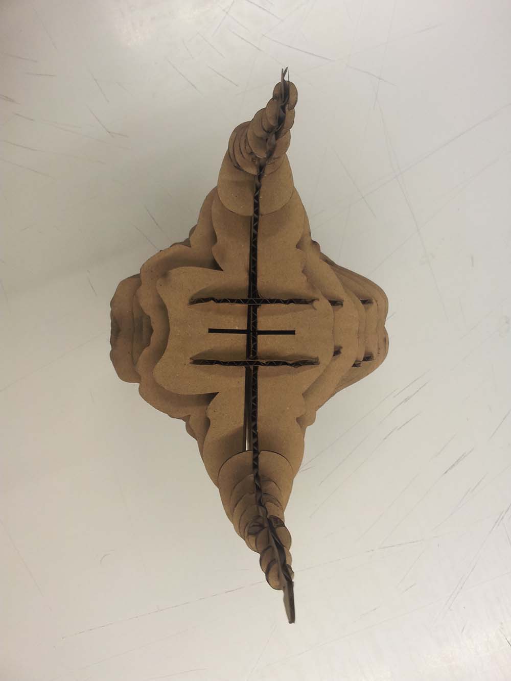
The assignment The assignment for this week was to build a 3D model composed of parts that could be cut in a laser-cut machine. One of the requierements was to document all the process of the design, preparation and cutting of the whole model. For the past years, during my career of architecture, I have developed several models with computer-controlled cutting, specially with the laser cut machine. You can check some of my models in my portfolio. As I did for the last week a 3D model of a bust of a monster with and advanced modelling plugin for Rhino, I decided that it was a good idea to represent this figure as a reak representation through a physical model. I have seen models like this made out of unfolded paper like origami, and other representation made of sections in several directions of the whole model. I decided that the best way to represent such a complex 3D model, was actually to build a model made of sections, some done horizontally and some others done vertically in both directions of the figure. I knew that the best way to do this, was using some parametric software. As I was using Rhinoceros for my 3D design, the most practical way was to use Grasshopper plugin for Rhino. I have used this software for several years, as it has become very popular in architecture. I mainly have used it for solar optimization of a building and for advanced modelling of shapes and roofs. I had some issues trying to install it, as I did not have the latest Rhino update, and as I was on a hurry for the delivery of the assignment, I decided that I could do it in the common way: creating 2D sections and think about the assembling between them. I drew some skecthes of which sections would be necessary for the whole model comprehension.
|
|
 |
 |
 |
  |
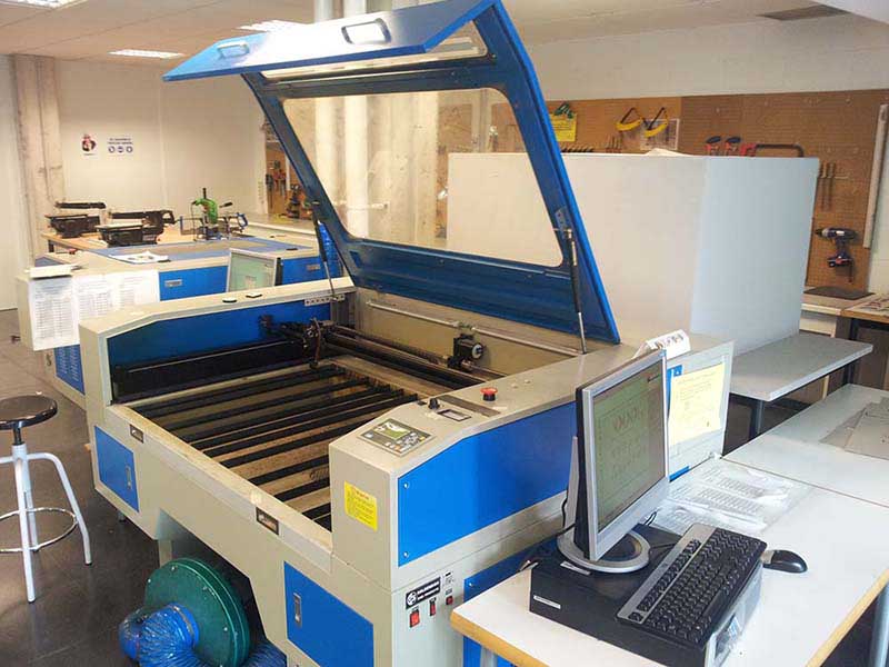
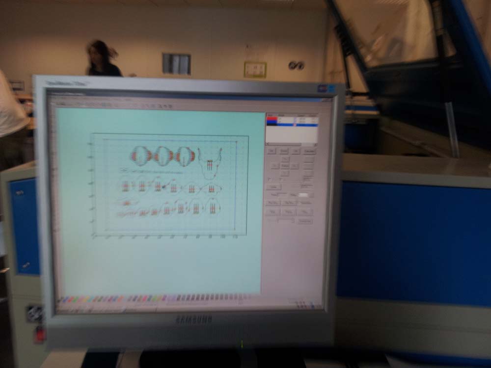
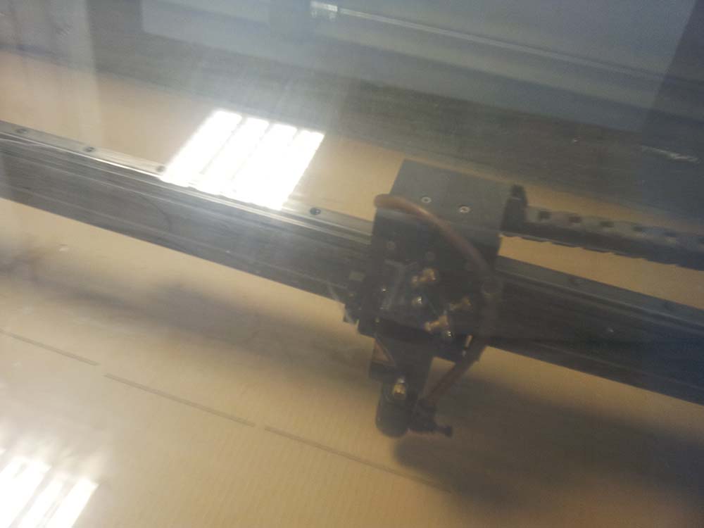
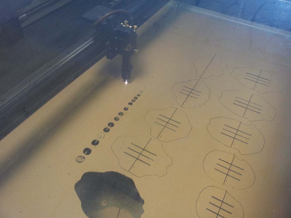
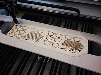
The laser cutting The machine that we have in our FabLab in Madrid is a GS Goldensign, imported from China. As it is located in a public space of the university, where all the students have access to it, there is a computer with the suitable software recommended by the manufacturer, and I was not allowed to install the software recommended by the course: Fab Modules. I used this machine many times, so the work ahead was very easy.
|
|
 |
 |
 |
 |
 |
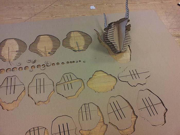 |
The assembling The assembly of a model like this is very easy. It is important to do some previous sketches and demos of what is going to bring out the laser-cut machine for us. If we do some previous tests of what is going to happen, we can succeed every time we do a model like this.
|
|
 |
 |
The mistakes The best thing to learn in this type of models, is to try to find out what mistakes could be undone with a previous organization:
|
|
 |
|
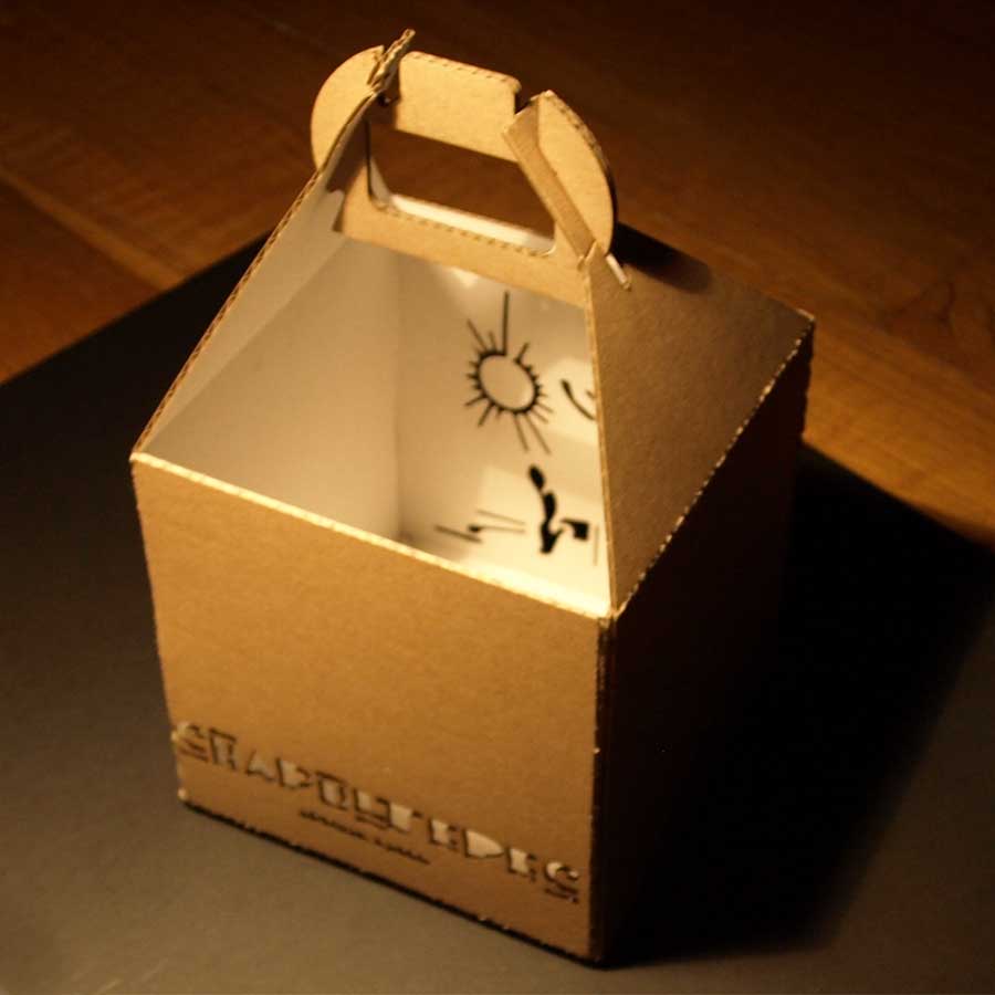
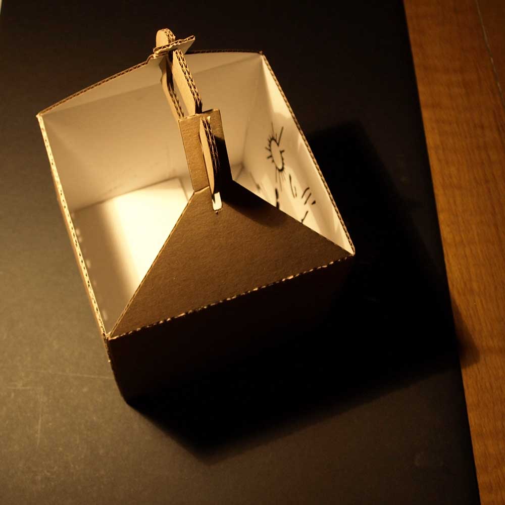
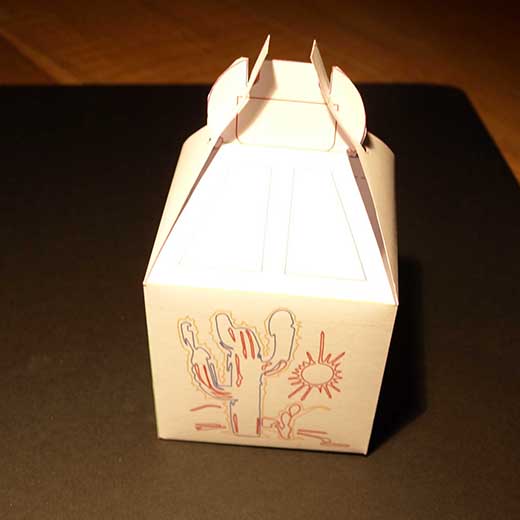
Other laser cut models Along my career I have done many models with this machine, so I feel kind of expert in this hardware. I graduated recently and I had some free time for doing other stuff that i was interested, here is ana example: - Beer 4 pack.- I am starting to brew beer in my house, and I designed and fabricated a box to bring 4 bottles at a time. After some designs and proofs done at home, I finally got into the final design and made the real model in the laser cut machine.
|
|
 |
 |
 |
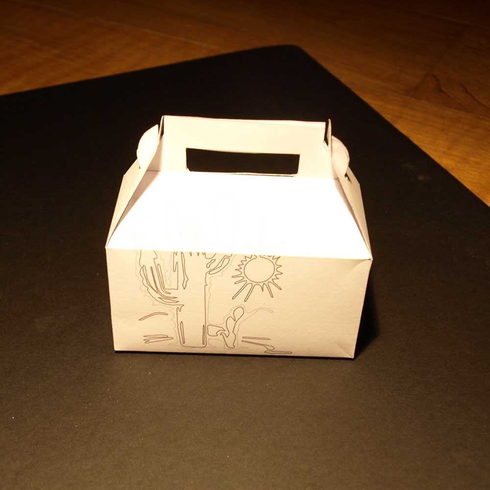 |
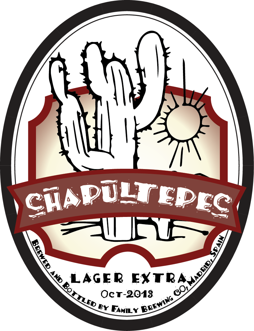
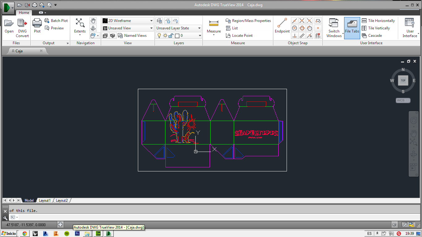
The model was made in order to bring 4 bottles of glass of 330 ml of beer, so the material and the assignment had to be strong enoough not to break, and easy to fold and assembly to the easy packaging of the beer. The design of the box was adapted from an existing one, but reduced from 6 to 4 beers packaging and enlarged as the bottles it held was only 200 ml. The design was vectorized in Adobe Illustrator from a pixelated PDF and then redrawn in AutoCAD with my design of the beer called CHAPULTEPEC. The name of the beer came from a family tradition as I have some descendents from Mexico, and Chapultepec is an important park and castle in the city of Mexico. |
|
 |
 |
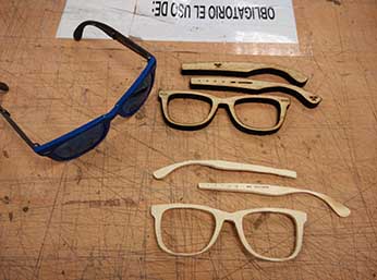
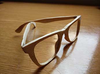
Wooden glases prototype (7/04/2014) This past weeks I wanted to do something for my own and for some gifts for my friends. Here ar two prototypes that I have done.
|
||
 |
 |
 |